|
SymbolType macro command |

  
|
| Show/Hide Hidden Items |
|
SymbolType macro command |
|
| Show/Hide Hidden Items |
Macro commands may be used either in macros or by sending the commands to DPlot via dynamic data exchange (DDE). Some commands are valid only in macros (noted by Macros Only). Commands sent to DPlot via DDE must be enclosed by square brackets [ ]. Macro commands should not include the brackets.
Command parameters shown in the descriptions below are placeholders for the actual values. Command parameters are either numeric values, equations that evaluate to numbers, or character strings. Character string parameters are always bound by double quotation marks. Equations must be preceded by an equals sign (=).
The pipe symbol (|) in the command syntax indicates that a parameter is optional, and should not be included in your macro unless otherwise noted.
All indices into arrays are 1-based, e.g. Curve1=1 refers to the first curve in a plot.
A 0x prefix for numbers in the descriptions below indicates hexadecimal notation; e.g. 0x0010 = 16.
![]() JR/Viewer indicates that the command is supported by DPlot Jr or DPlot Viewer.
JR/Viewer indicates that the command is supported by DPlot Jr or DPlot Viewer.
![]() JR/Viewer indicates that the command is NOT supported by DPlot Jr or DPlot Viewer.
JR/Viewer indicates that the command is NOT supported by DPlot Jr or DPlot Viewer.
[SymbolType(curve,type)] |
|
Sets the symbol type. Set type to 0 for no symbols. Valid type values are shown below. If curve is set to -1, this command changes the symbol style used by all curves/data sets.
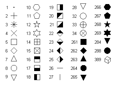
Symbols 28 and 284 are identical to symbols 9 and 265, respectively, with the exception of vertical alignment. Symbols 9 and 265 are placed such that the geometric center of the triangle is at the data point. Symbols 28 and 284 are vertically aligned with symbols 7 and 263.
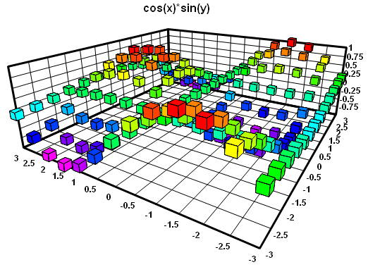
Symbol type 389 is only available in 3D scatter plots when "Symbol size in Z units" (see SymbolSizeUnits) is selected. In that case, this symbol (unlike all others) will be drawn using the perspective settings for the plot. To control perspective programmatically, use the ContourView command.
|
You can also specify a character from the Wingdings, Wingdings 2, or Wingdings 3 fonts to use as a symbol. Note: These fonts must be installed on the end user's system for this feature to work properly. In this case type is the character code plus 512 (0x0200) for Wingdings, 768 (0x0300) for Wingdings 2, or 1024 (0x0400) for Wingdings 3. For example type = 0x0393 (decimal 915) specifies character 0x93 (147) from the Wingdings 2 font. Character codes should be greater than 32 (space) and must be less than or equal to 255 (0xFF).
You can view any of the Wingdings fonts using the Character Map applet that is installed with Windows (generally under Programs>Accessories), or by selecting the Symbol/Line Styles command on the Options menu and clicking the Other... button.
For 3D/4D surface plots, setting the symbol type to a non-zero value is equivalent to checking the "Data points" box on the Contour Options dialog. The actual type is ignored in this case; symbols will always be filled black squares. You can control the size of the squares with the SymbolSize command.
____________________________
See also
Symbol/Line Styles menu command
Page url:
https://www.dplot.com/help/index.htm?symboltypecommand.htm